Case study
Semi-Automatic Produce Slicer
A team-designed slicer that uses a cam-follower mechanism to turn manual rotary input into a reciprocating cutting stroke. I designed the housing and the pusher.
- Role
- Housing and pusher design (team project)
- Affiliation
- ME 1700, Fall 2025, team of four
- Tools
- SolidWorks
- Status
- Status: Designed in CAD
Problem and constraints
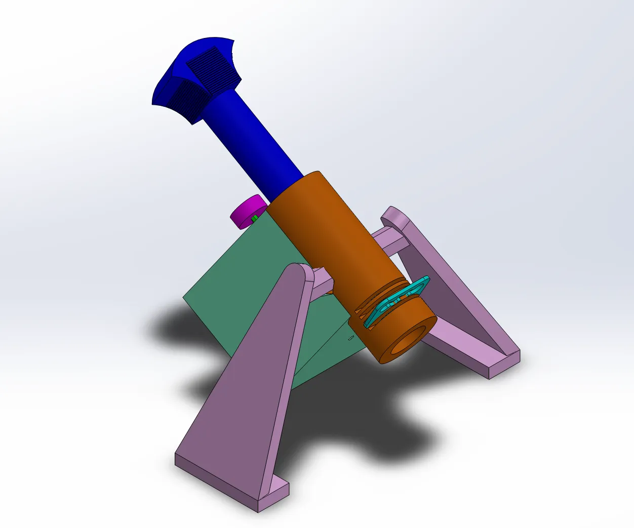
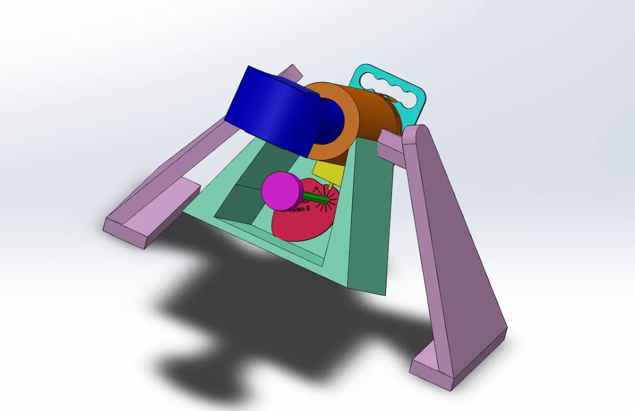
The slicer cuts soft vegetables such as cucumbers and zucchini. A cam-follower system, driven by a manually rotated rod, converts that rotary input into linear reciprocating motion. The mechanism automates the cutting stroke, while the user feeds by hand with a pusher, which the design uses for user safety.
The brief was open ended: the only requirement was to build a mechanism that uses a cam. It set no numeric specifications.
Approach
My parts were the housing and the pusher. The cam, the base supports, and the remaining parts were my teammates’ work.
Housing
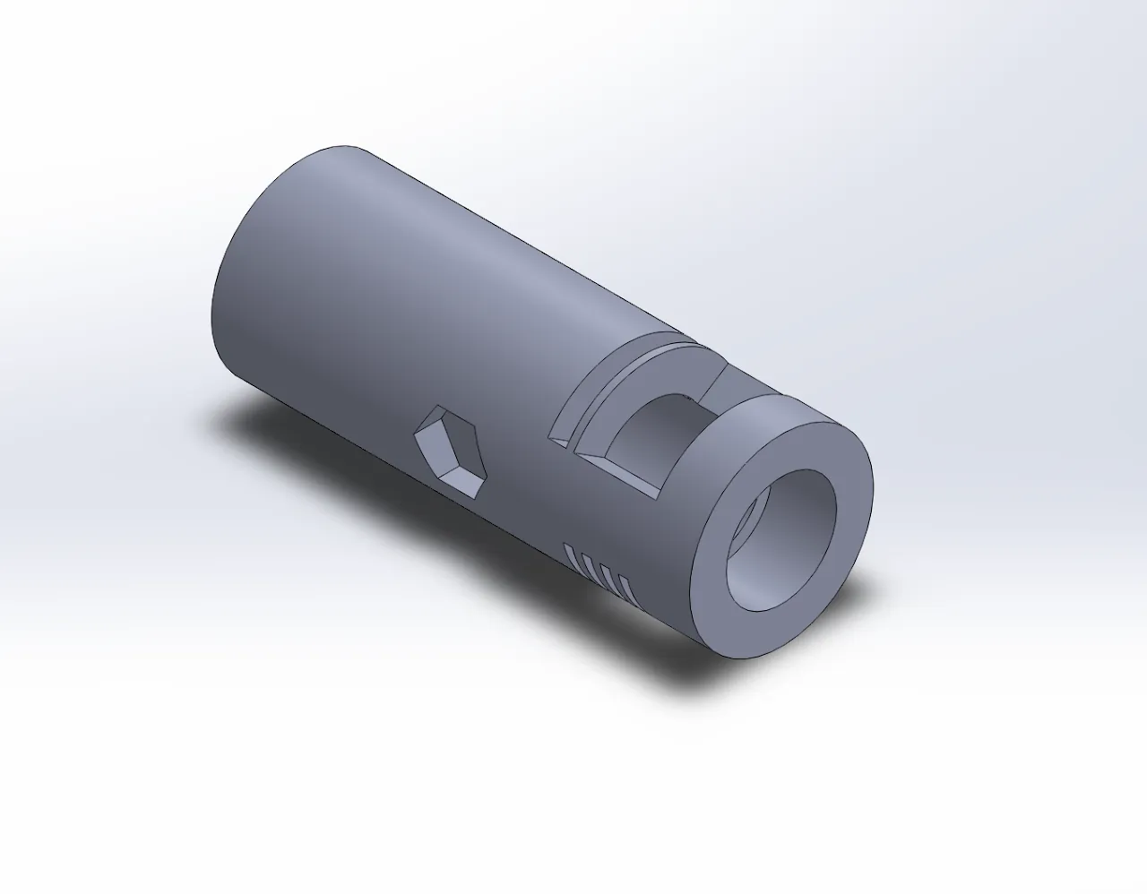
The housing is the central cylinder of the slicer and the main fixture for the slicing mechanism. I designed it with hexagonal mounting interfaces, slotted clearances for the blade path, and an adjustable spacer system at the intake to control cut thickness.
Pusher
I also designed the pusher, the part the user operates for the manual feed.
Result
The slicer exists only as CAD. It was not physically built. The native SolidWorks files are lost, and the three renders on this page are the only remaining record, so there is no 3D model or downloadable CAD for this project.
What I’d do differently
I would make the slicer bigger and stronger so it could handle more types of fruits and vegetables. I would also simplify the overall design compared with what we built.