Case study
Brake Pedal Connector Redesign
Redesign of a 7075-T6 aluminum brake pedal connector around fixed mounting interfaces, with a linear static FEA of the redesign.
- Role
- Component design and structural analysis
- Affiliation
- Iowa State Formula SAE Electric
- Tools
- SolidWorks, SolidWorks Simulation
- Started
- Aug 2026
- Status
- Status: Analyzed
Key results
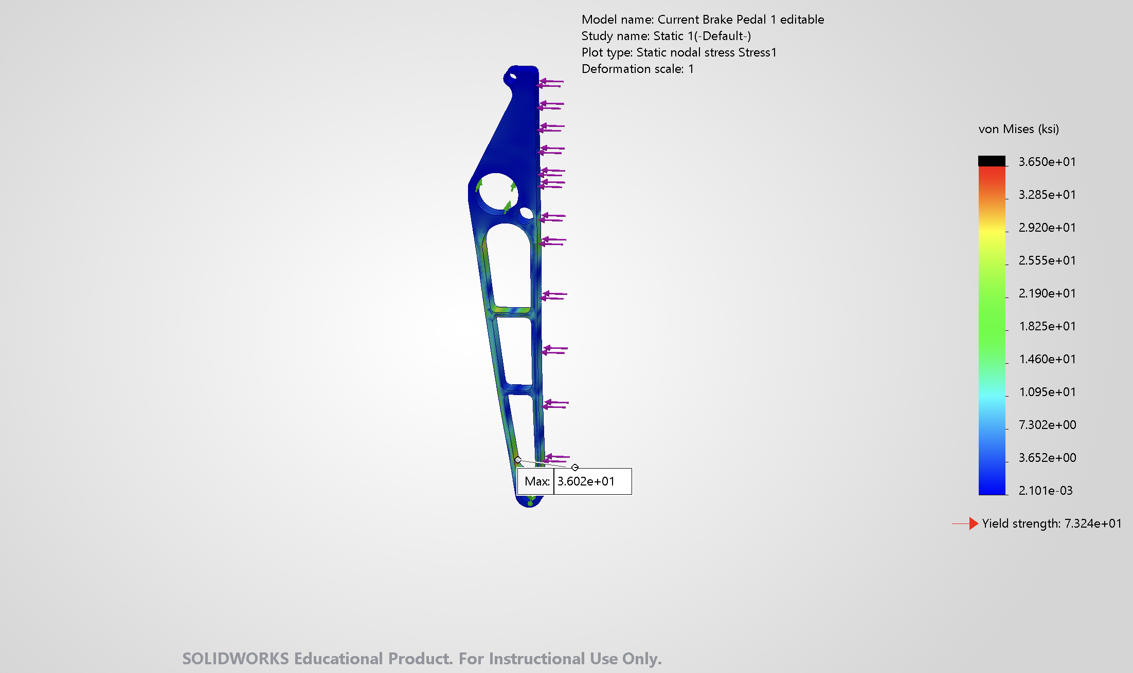
- Max von Mises stress
- 36.0 ksi
- 248 MPa, nodal
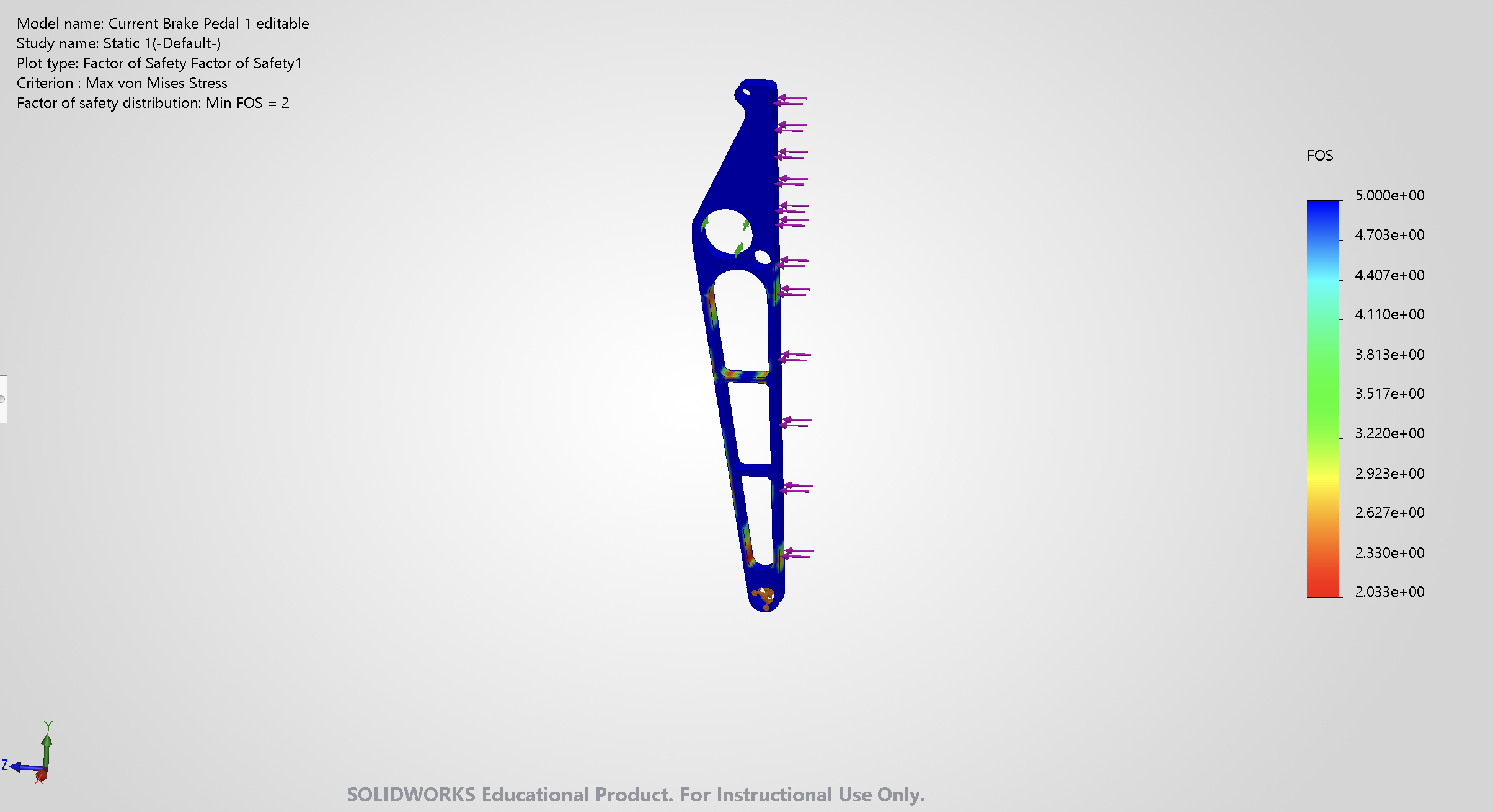
- Min factor of safety
- 2.03
- Von Mises, against 505 MPa yield
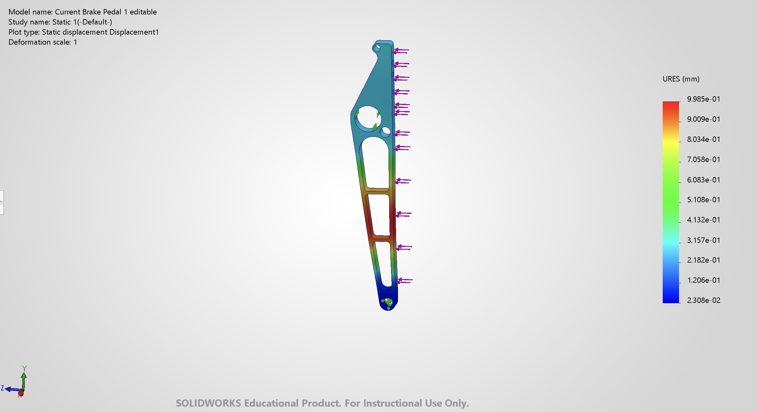
- Max displacement
- 0.039 in
- 0.9985 mm
- Mass
- 0.2144 lb
- 97.2 g
Problem and constraints
The brake pedal connector is a 7075-T6 aluminum part in the Formula SAE Electric brake pedal assembly. I started from an existing SolidWorks part and engineering calculations provided by a subsystem lead.
The large mounting holes are fixed interfaces and could not move. The redesign was therefore limited to the internal connecting beams and how material is distributed between them.
Loading 3D model
Approach
I explored three internal layouts: truss, pocketed, and X-shaped (two diagonal members). Each keeps a direct load path between the fixed interfaces and removes material from low-load regions. I used radiused transitions and sized fillets to control stress concentrations while keeping the part machinable.
Analysis
I performed force, shear, and moment analysis to identify the critical braking and side-loading conditions, including out-of-plane bending on the pedal assembly. I then ran a linear static FEA on the redesigned connector for a single load case, set up as described below. The FEA does not model the side-loading or out-of-plane bending conditions.
Study and material
The study below covers the redesign, the version shown in the viewer above. It is a linear static study (Static 1) in SolidWorks Simulation 2026: small displacement (large displacement off), with automatic solver selection (FFEPlus).
| Property | Value |
|---|---|
| Material | 7075-T6 (SolidWorks library entry “7075-T6 (SN)”), linear elastic isotropic |
| Elastic modulus | 10,440 ksi (72 GPa) |
| Poisson’s ratio | 0.33 |
| Density | 0.1015 lb/in³ (2,810 kg/m³) |
| Yield strength | 73.2 ksi (505 MPa) |
| Tensile strength | 82.7 ksi (570 MPa) |
| Failure criterion | Max von Mises stress (default) |
| Redesign mass properties | 0.2144 lb (97.2 g), volume 2.1116 in³ |
Loads
One load case: 450 lbf (about 2,002 N) total, applied normal to the three faces along the arm’s edge where the pedal face mounts. The 450 lbf value is an estimate based on driver input, not a measured value or a rule-derived value.
Boundary conditions
- Pivot hole at the lower end: a cylindrical-face fixture with radial and axial translation fixed and tangential translation free, so the arm can rotate about the pivot.
- Large hole: a reference-geometry fixture on the hole face, referenced to a line from the Brake Motion Ratio sketch, with 0 mm along that line. It restrains the hole face against translation along the pushrod line of action, standing in for the master cylinder reaction.
Mesh
Solid mesh, blended curvature-based mesher, high quality. Element size 0.0408 to 0.1225 in (1.04 to 3.11 mm), giving 12,276 elements and 22,349 nodes. Maximum aspect ratio is 14.2; 98% of elements have an aspect ratio under 3, 0.04% are above 10, and there are no distorted elements. No mesh convergence study was done.
Result
| Metric | Value |
|---|---|
| Max von Mises stress (nodal) | 36.0 ksi (248 MPa) |
| Minimum factor of safety (von Mises) | 2.03 |
| Max resultant displacement | 0.039 in (0.9985 mm) |
| Mass | 0.2144 lb (97.2 g) |
Redesign results
All values are nodal results at true deformation scale.
- Stress. Max von Mises stress is 36.02 ksi (248 MPa), at the lower end near the pivot hole. This peak sits next to the constrained pivot face and may be sensitive to how that boundary condition and the mesh are defined.
- Factor of safety. Minimum FOS 2.03 on peak nodal von Mises stress against 505 MPa yield, in the pivot hole region. The webs and slot corners in the lower half of the arm are roughly 2.3 to 3, and most of the upper arm is above 5.
- Displacement. Max resultant displacement is 0.039 in (0.9985 mm).
Limitations
This is a single load case. There is no fatigue analysis, no contact or fastener modeling, and no mesh convergence study.
The redesign has been designed and analyzed only. It has not been manufactured yet.
Related: DOT 4 reservoir spacer material selection
I compared polyethylene, PTFE, and PEEK for a spacer on the DOT 4 brake-fluid reservoir. The criteria were chemical compatibility with glycol-based brake fluid, dimensional stability, mechanical properties, durability, and manufacturability. I focused on unfilled Victrex PEEK 450G as the candidate and prepared the material-selection reasoning for the team lead. Approval and fabrication are not yet confirmed.